Solid-State Vs. Tube Amplifiers (Pre, Power & Guitar Amps)

Audio amplifiers are required in nearly all playback environments and many recording situations as well. There are plenty of amplifier types out there, and a major distinction between amplifiers is the use of solid-state circuitry versus tube circuitry.
What are the differences between solid-state and tube amplifiers? Solid-state amps use solid-state (transistor-based) amplifier circuits, while tube amps use vacuum tube amplifier electronics. This difference is apparent in power amps, preamps and other amplifier types as well. It also yields other general differences between solid-state and tube amps.
In this article, we'll describe vacuum tube and solid-state amplifiers in detail and get into each of the general differences we should expect to find between the two different amplifier types.
Related article: Full List: Audio Amplifier Brands/Manufacturers (+ Examples)
If you'd like to support my work and learn more about music production, please consider subscribing to my Substack.
Table Of Contents
- What Are Amplifiers?
- What Are Tube Amplifiers?
- What Are Solid-State Amplifiers?
- The Differences Between Solid-State & Tube Amps
- Solid-State & Tube Preamplifiers
- Solid-State & Tube Power Amplifiers
- Solid-State & Tube Guitar Amplifiers
- Solid-State & Tube Headphone Amplifiers
- Hybrid & Integrated Amplifiers
- Built-In Amplifiers
- What About Digital Amplifiers?
- Related Questions
What Are Amplifiers?
Before we get into our discussion about solid-state and tube amplifiers, let's first define what an amplifier is.
An amplifier (informally called an “amp”) is an electronic device designed to increase the amplitude of a signal.
A signal is a time-varying voltage or current. Analog audio signals, which are amplified by a variety of different audio amplifiers, are largely defined by their voltage (strength/amplitude) within the audible range of human hearing (20 Hz – 20,000 Hz).
Audio amplifiers, then, are largely tasked with amplifying the voltage of the audio signal between 20 Hz and 20,000 Hz.
Amplifiers are two-port electrical circuits (input and output). They use electric power from an external power source (the power mains of a building, a battery, etc.) to increase the amplitude of a signal.
A signal at the input terminals of the amplifier is amplified, and a proportionately higher-amplitude signal is produced across the output terminals of the amplifier.
The amount of amplification the amplifier is capable of is dependent on the power source and the electronic design of the amplifier.
The measurement of the amplifier's amplification is defined by gain, which is the ratio of output voltage to input voltage. Note that, technically speaking, the idea of gain can also be applied to current and power, but the strength of audio signals is generally defined by voltage.
Amplification happens when gain is greater than 1. Though gain is defined as the ratio of output to input, it is often described in decibels, which is a logarithmic ratio.
Amplifiers come in all sorts of shapes, sizes, and types. They can be separate units or built into other devices.
Amps are often categorized by the types of signals they are tasked with amplifier and their position in the audio signal chain.
In my article Passive Amplifiers Vs. Active Amplifiers (Sound & Audio), I talk about the various types of active amplifiers (the electrical devices we'll be discussing in this article). These types include:
- Power Amplifier: amplifies line level signals from playback devices to speaker level signals that drive a loudspeaker.
- Preamplifier: amplifies low-level signals (often from microphones or phono cartridges) into line level signals for typical recording and processing.
- Integrated Amplifier: the combination of a preamplifier and a power amplifier into a single unit.
- Receiver: an integrated amplifier with a radio receiver.
- Car Amplifier: a power amplifier that is designed to drive car speakers and run on the car battery/alternator.
- Instrument (Guitar, Bass, Etc.) Amplifier: a preamp and/or power amplifier designed to amplify the hi-Z output signals from instrument pickups.
- Headphone Amplifier: amplifies line level signals to signals that will properly drive a pair (or several pairs) of headphones.
- Microphone Preamplifier: a preamplifier designed to amplify mic level signals (from microphones) into line level signals for typical recording and processing.
- Impedance Converter Amplifier: an amplifier that is more so concerned with altering the impedance of a signal than applying gain to the voltage of the signal. These amps are often found in condenser microphones.
- Distribution Amplifier: a unit that splits a signal input signal into multiple output signals of the same amplitude.
- Solid-State Amplifier: an amplifier that uses solid-state electronics.
- Tube Amplifier: an amplifier that uses tube electronics.
- Digital Amplifier: an amplifier that uses digital signal processing to amplify the digital audio signal.
In this article, we'll obviously be focusing on solid-state and tube amplifiers. However, it's important to know the various amplifier types since solid-state and tube electronics can be used in these other types.
What Are Tube Amplifiers?
As the name suggests, tube amplifiers utilize vacuum tubes to amplify their input signals.
The first practical electrical amplification device was the triode vacuum tube. It was invented in 1906 by the American inventor Lee De Forest. Triode tubes were used to produce the first amplifiers circa 1912 though the term “amplifier” only came to be around 1915 when triodes, rather than relays, became common devices to boost signals.
Tube electronics were used in nearly all amplifiers until the 1960s when solid-state amplifiers hit the market and started becoming more popular.
The McIntosh MC2152 is a 2-Channel Vacuum Tube Amplifier.

McIntosh
McIntosh is featured in My New Microphone's Top 11 Best Power Amplifier Brands In The World.
How do tube amplifiers work? Let's begin by understanding the triode vacuum tube.
The Triode Vacuum Tube
The triode vacuum tube (the simplest form of a tube amp) is a voltage-driven device with 3 electrodes inside a glass or ceramic vacuum tube (hence the name).
Let's have a look at a simplified illustration of a triode tube:

The 3 electrodes are known as:
- A: Anode (plate) – positively charged
- K: Cathode – negatively charged
- G: Grid
- H: Heater (not an electrode)
The power supply of the tube amplifier causes the heater to heat the vacuum tube to operating temperature. It also charges the anode and cathode plates positively and negatively, respectively.
Note that the tube must be a vacuum and hold no air, or else the heat, combined with oxygen, would burn up the elements. Having a vacuum also allow electrons to move freely.
As the tube is heated up, the cathode (electron donor) begins shedding electrons via thermionic emission. These negatively charged electrons are repelled by the negatively charged cathode and attracted to the positively charged anode (plate). They flow unimpeded from the cathode to the anode.
This flow of electrons is better known as an electrical current.
Once powered/heated, the vacuum tube will have a voltage across its anode and cathode that can be tapped as an output.
The grid electrode is where things get really interesting for the triode design.
The control grid acts as a sort of mesh between the cathode and anode. Its holes allow electrons to pass through it. By adjusting the voltage applied to the grid, we control the number of electrons flowing from the cathode to the anode and modulate the voltage across the vacuum tube.
The input signal of the amplifier is applied to the control grid. This AC voltage/signal at the grid modulates the stronger signal at the plate.
What happens, then, is the relatively low-level input signal of the amplifier controls a relatively high-level output signal.
This makes the triode tube invaluable not only as an amplifier but also as an impedance converter. With a triode, a low-level high-impedance input signal (at the “input” or grid of the tube) will modulate a high-level low-impedance signal (at the “output” of the tube).
In an ideal world, the triode would output an amplified signal without any distortion.
This output signal from the tube is then typically sent through an output transformer before it is “outputted” by the amplifier. The step-down output transformer drops the impedance further to improve the damping factor and signal transfer to the connected device (a loudspeaker in the case of a power amp and a line level input in the case of a preamp).
The step-down output transformer also boosts the current of the output signal while dropping the voltage.
What Are Solid-State Amplifiers?
Solid-state amplifiers, as the name suggests, are amplifiers that utilize solid-state electronics to amplify their input signals.
The birth of solid-state electronics (though first conceptualized by Julius Edgar Lilienfeld in 1925) only came about with the invention of the first transistor by scientists at Bell Labs in 1947.
Solid-state electronics began to largely replace relatively bulky and expensive tube electronics in the 1960s and 1970s. Today, transistors are used in digital devices (including digital amplifiers), and the modern usage of tube electronics is pretty limited to audio technologies.
The Crown Audio XLi 2500 is a popular solid-state stereo power amplifier.

Crown Audio
Crown Audio is featured in My New Microphone's Top 11 Best Power Amplifier Brands In The World.
How do solid-state amplifiers work? Let's begin by comprehending the bipolar junction transistor and the operational amplifier.
The Bipolar Junction Transistor
A bipolar junction transistor (BJT) is a type of [solid-state] transistor. It is a three-terminal semi-conductive device that uses both electrons and holes as charge carriers.
A BJT works by allowing a small current injected at its base terminal to control a much larger current flowing between the two other terminals (the emitter and collector).
The 3 terminals of a BJT are:
- Base
- Collector
- Emitter
Having a small signal control a larger signal allows the BJT to amplify a signal, which is what we're concerned with. It also allows for switching (on/off), which is a major factor in digital processing (binary on/off – 1s/0s).
BJTs use two junctions between two semiconductor types:
- N-type: doped with impurities the provide mobile electrons.
- P-type: doped with impurities the provide holes for mobile electrons.
Bipolar junction transistors are designed as either NPN or PNP.
- NPN: two P-type junctions (at the collector and emitter terminals) that share a thin N-type region (at the base terminal).
- PNP: two P-type junctions (at the collector and emitter terminals) that share a thin N-type region (at the base terminal).
Let's have a look at the schematic symbols for both types of bipolar junction transistors:

The collector-emitter current can be controlled by the base-emitter current.
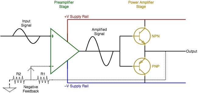
In a solid-state power amplifier circuit, the pre-amplified audio signal is applied to an NPN and a PNP bipolar junction transistor.
Two power rails are used to power the amplifier. The positive power rail applies a positive voltage across the collector-emitter of the NPN BJT. The negative power rail applies a negative voltage across the collector-emitter of the PNP BJT.
This can be seen in the simplified schematic of a solid-state amplifier pictured below:

We see the two BJTs in yellow.
The output of the amplifier is driven by only one power rail at any given time. When the output signal is positive, it is effectively connected to the +V supply. When the output signal is negative, it is effectively connected to the –V supply.
Audio signals are generally in the range of 20 Hz to 20,000 Hz, and the switching between power supply rails happens very rapidly!
When the +V supply is driving the amplifier output, the connected speaker moves outward, and when the –V supply is driving the amplifier output, the connected speaker moves inward. This is basically how speakers work as transducers.
A relatively low-level audio signal is connected to the two BJTs in parallel.
The NPN and PNP are polarity complements of each other. When biased correctly, these transistors will provide current from the +V or –V supply rails to drive the amplifier output.
When the input signal is positive, the NPN will allow a larger current through to the output via the +V supply.
When the input signal is negative, the PNP will allow a larger current through to the output via the –V supply.
The transistors (transfer resistors) do not simply switch between the +V and –V supplied to send output current. Rather, they mimic the input waveform and continuously adjust the amount of current sent through to the output.
Output transistors do not increase the strength of the signal. They increase the current of the signal to drive the speakers effectively.
This is oversimplified, of course, but it gives us a basic understanding of how solid-stage amplifier output stages work.
The Operational Amplifier
Another important component of a solid-state amplifier is the operational amplifier (op-amp).
An operational amplifier is a voltage amplifying device designed to be used with external feedback components between its output and input terminals. It is a high-gain electronic voltage amplifier with a differential input and, typically, a single-ended output.
Here is a simple op-amp schematic symbol with appropriate labels:

Note that actual op-amps are often made of a complex circuit that includes a variety of transistors.
Let's have another look at our simplified solid-state amplifier circuit:

The to-be-amplified input audio signal is applied to the non-inverting (+) input of the op-amp.
A volume control is typically available to adjust the input signal's voltage before it reaches the op-amp. The op-amp itself will have a fixed gain ratio equal to R1/R2 +1 according to the negative feedback loop resistors:
Typically the gain of an op-amp in a solid-state amplifier is between 20:1 and 40:1.
It's important to note that, like any amplifier, the op-amp is an active device that requires power to function. This power is provided via the +V and –V power supply rails.
As an aside, the output is connected to the inverting terminal of the op-amp. This drops the output impedance of the amplifier way down, allowing for an amplifier high damping factor and excellent signal/voltage transfer from the amp to the speaker via impedance bridging (load impedance of the speaker is much higher than the source impedance of the amplifier output).
The Differences Between Solid-State & Tube Amps
Now that we know about tube and solid-state amplifiers, let's get into the meat of this article and look at the general differences between solid-state and tube amplifiers.
The table below shows the general differences. The subsequent paragraphs will go into detail about each of these general differences.
| Solid-State Amplifier | Tube Amplifier |
|---|---|
| Transistor-Based Amplifier Circuitry | Vacuum Tube Amplifier Circuitry |
| Current-Driven | Voltage-Driven |
| Output Transformers Are Optional | Output Transformers Are Required (Power Amps) |
| Relatively Less Expensive (Watts/Dollar) | Relatively More Expensive (Watts/Dollar) |
| Less Need For Upkeep | More Need For Upkeep |
| More Reliable | Less Reliable |
| More Difficult To Troubleshoot | Less Difficult To Troubleshoot |
| Generally More Detail | Generally More Character |
| Higher Damping Factors | Lower Damping Factors |
| Harsher Distortion: Transistor Distortion | Smoother Distortion: Tubes Saturation |
| More Consistent Tone | Tone Is Altered As Tubes Age |
| Generally Quieter Per Watt | Generally Louder Per Watt |
| Temperature-Independent | Temperature-Dependent |
| Generally Lighter Weight | Generally Heavier Weight |
Solid-State Vs. Tube Circuitry
This one is obvious and has already been discussed in this article.
Solid-state amplifiers have solid-state (transistor-based) amplifier circuits.
Tube amplifiers have vacuum tube-based amplifier circuits.
Current-Driven Vs. Voltage-Driven
A vacuum tube is a voltage-controlled device. The voltage (of the input signal) is applied to the grid of the triode vacuum tube and is used to control the output of the vacuum tube across its cathode and anode electrodes.
The op-amp and dual bipolar junction transistors used in a basic solid-state amplifier circuit are current-controlled as a whole. The base-emitter current effectively controls a larger “amplified” current across the collector-emitter.
At the core of their amplification circuits, tube amps are voltage-controlled, and solid-state amps are current-controlled.
Output Transformers
Tube power amplifiers use step-down output transformers to convert the high-voltage, low-current output signal of the tube circuit into a low-voltage, high-current signal that will properly drive the speaker. Voltage alone cannot drive a speaker, especially when the amplifier output impedance is high.
At the same time, the step-down output transformer will drop the output impedance of the tube amp, yielding a better damping factor and better voltage/signal transfer between the amp and the speaker(s) due to better impedance bridging.
On top of that, the output transformer will block any DC voltage, allowing only the AC audio signal to pass through. This will help with protection and noise.
Note that, while power tube amps require output transformers, tube preamplifiers do not require output transformers and typically will not have them (unless part of an integrated tube amplifier).
Many early solid-state amplifiers utilized output transformers, but most modern solid-state amps go without.
There's no need for an output transformer in solid-state amplifiers. Their outputs tie back to the inverting input of the op-amp for negative feedback and drop the output impedance well below any tube amplifiers.
They also do not require the added protection from DC since the output is already protected via the solid-state BJTs.
Price
Transistors revolutionized the world in many ways. A major part of their success has to do with their smaller size, ease of manufacturing, and cost of production.
If they are of high quality, the components that makeup tube amplifiers (vacuum tubes, transformers, etc.) cost significantly more than any high-quality components used in a solid-state amplifier.
This is all a simplification; there are certainly inexpensive tube amps and expensive solid-state amps.
However, in general, tube amps will cost more than their solid-state counterparts.
This is particularly true of power amplifiers, where the average power-to-cost ratio (watts per dollar) is higher in solid-state amps.
Note that this price difference also holds true with preamp and integrated amps.
Upkeep
Overloading/damaging aside, tube amplifiers will require more upkeep than their solid-state counterparts.
Vacuum tubes, even under normal running circumstances, will eventually burn out. Op-amps and BJTs, however, will last a very long time before ever needing replacement.
This is a concern for all tube audio equipment.
Reliability
This ties in nicely with upkeep.
As mentioned, tubes will slowly but surely burn out. As the vacuum tubes age, their effectiveness will change, and the performance of the amplifier may be altered.
This can be considered a disadvantage in terms of reliability.
Solid-state amplifiers, in kept in working condition, will sound the same for ages.
Tubes are also more fragile and sensitive to temperature than are solid-state amplifier circuits.
We can depend on solid-state amplifiers more than tube amps. This is particularly true of mobile rigs where the amplifiers are constantly being moved around (and, therefore, perhaps subjected to physical impact and temperature variation).
Troubleshooting
Tube amplifier circuits are relatively simple, and tubes are often designed to be replaced with relative ease.
If there's an issue with a tube amplifier, we can bet it has to do with the tubes or the wiring to the tubes.
Solid-state amplifiers have more components and are often produced on circuit boards. Understanding the circuitry and troubleshoot effectively takes patience and determination.
Detail Vs. Character
Modern technology has made it so that solid-state amplifiers can portray the same “character” as tube amps.
In the early days of solid-state amplifiers, many considered the new alternatives to sound flat and lifeless. Tube amps, many would say, had the sonic character that was pleasing to the ears.
To this day, in general, subjective terms, many would argue that tube amps do have more character (they colour the sound in a pleasing way) while solid-state amps are cleaner and more detailed.
Again, this is a general statement.
Damping Factor
The damping factor of a power amplifier refers to the ratio between the load impedance (nominal speaker impedance) and the source impedance (the output impedance of the speaker).
It is a determinant of how well the amplifier will control the drivers of the speaker it is connected to and driving.
The higher the damping factor, the more control the amp will have over its connected speaker. High damping factors come with low amplifier output impedance.
In general, a damping factor above 20 means the amplifier should control the speaker with great accuracy.
Solid-state amplifiers naturally have low impedance and damping factors well above 20. This is due to the negative feedback loop of their op-amps at the output.
Tube power amplifiers, however, have their step-down output transformers. These transformers often only get the output impedance down to achieve a damping factor between 10 – 20 (sometimes it's even lower, and sometimes it's higher).
Tube power amplifiers are still designed to drive speakers. However, solid-state amps will technically have more control over their speakers than tube amps.
For more information on amplifier damping factor, check out my article What Is Damping Factor Between An Amplifier & Loudspeaker?
Distortion & Tone
Overdriving amplifiers can have horrendous effects. It can overheat and damage the amplifier and/or speaker and will often cause undesirable distortion in the audio signal.
However, some amount of saturation distortion can add a pleasing sonic character to the audio.
This smooth saturation is part of the “tube sound”.
See, tubes begin distorting very slowly and produce even harmonics when overdriven, which are pleasing to the ear.
Transistors, on the other hand, clip more abruptly and may produce odd harmonics that are unmusical and not pleasing to the ear.
Loudness
This ties into the distortion differences between tube and solid-state amplifiers.
Given the same power output, tube amplifiers generally have the effect of sounding louder.
This is because transistors distort rather abruptly. It's easy to tell when a solid-state circuit is pushed past its headroom because the distortion is audible.
Tube amplifiers, conversely, can be pushed above their “limit” with what are often described as “pleasing” results. A tube driven above its limit will begin saturating and producing added even harmonics to the sound.
The output power will be the same, but a sort of compression effect will make the overall signal sound much louder.
Analog Vs. Digital
Vacuum tubes are purely analog.
Transistors, which are the basis of solid-state electronics, are also the building blocks of digital electronics. Therefore, technically speaking, “solid-state” transistor-based amplifiers can be of the digital variety.
However, digital amplifiers are typically referred to properly as “digital amplifiers”. The term “solid-state amplifier” typically refers to analog solid-state amplifiers.
Related article: Are Audio Amplifiers Analog Or Digital Devices?
Temperature
All electronics are prone to failure when pushed past certain temperature points (particularly at high temperatures due to heat dissipation).
However, tubes are more sensitive to temperature than solid-state electronics.
Look closely at your amplifier's operational temperature range specifications (especially the tube amplifiers) and ensure they operate within their proper ranges.
Tubes are notably sensitive to cold and may crack if heated from too cool a temperature. When transporting tubes in the cold, ensure ample time for them to get to room temperature before turning them on.
Weight
Tube electronics are notoriously bulky and heavy.
A solid-state amp with similar specifications will generally weigh much less than its tube complement.
Solid-State & Tube Preamplifiers
Preamplifiers can be designed with solid-state or tube electronics though most modern preamps are solid-state.
Preamplifiers are more concerned with voltage gain than with increasing power at their outputs (as opposed to power amplifiers).
Tube circuits work well to boost gain and add musical character to the audio signal at the same time. Solid-state preamps are typically less expensive, more compact, and cleaner.
Note that balanced inputs of preamplifiers (and other amplifiers) require a differential amplifier at the input to sum up the differences between the positive and negative polarity conductors of the balanced connection. Balanced audio yields better noise specifications due to common-mode rejection (the cancelling out of any identical noise/interference on the positive and negative polarity conductors).
Preamplifiers come in a variety of types, including phono preamps, instrument preamps and microphone preamps.
For more information on microphones preamplifiers, check out my article What Is A Microphone Preamplifier & Why Does A Mic Need One?
Solid-State & Tube Power Amplifiers
We've mostly been discussing power amplifiers up to this point.
Solid-state power amplifiers are the norm nowadays. They are well-designed to handle high-level signals and have low output impedance to drive loudspeakers with ease.
Solid-State & Tube Guitar Amplifiers
A big topic in guitar amplifier selection is to go with a tube or a solid-state amplifier.
Tube amps are generally accepted to sound louder and more musical due to their saturation and compression characteristics when overdriven. This is often heard to be a good thing, especially with guitar tones that benefit from extra grit.
However, solid-state amps can be designed with superb modelling and sound just as good and “crunchy” as overdriven tube amps.
A tube guitar amp will often have a tube preamplifier to add gain and character to its sound, followed by a solid-state power amplifier that will get the “tube sound” up to a level that can more effectively control the amp's connected loudspeaker(s). This is called a hybrid amplifier.
Solid-State & Tube Headphone Amplifiers
Headphone amplifiers can also have tube or solid-state electronics.
These amplifiers take line level signals and amplify them and adjust their impedances to drive headphones properly.
For more information on headphone amplifiers, check out my article What Is A Headphone Amplifier & Are Headphone Amps Worth It?
Hybrid & Integrated Amplifiers
An integrated amplifier combines a preamp and a power amp into a single unit.
Integrated amplifiers are common in home entertainment systems (as amplifiers and receivers) and the aforementioned guitar amps (and other instrument amplifiers).
Though we can sometimes find an integrated amplifier that has tube electronics at both stages, it's much more common to find solid-state integrated amps.
As we've discussed, hybrid amplifiers typically have tube preamplifiers and solid-state power amplifiers rather than the other way around. The tube preamp is designed to shape the sound and give the input signal some character, while the solid-state circuit is designed to do the heavy lifting necessary to drive the loudspeaker(s).
Built-In Amplifiers
Many active audio devices have built-in amplifiers.
For example:
- Mic inputs in audio mixers will have mic preamplifiers.
- Active mixers have built-in power amplifiers at their outputs to boost line level signals up to speaker level.
- Active speakers have built-in power amplifiers at their inputs to boost line level signals up to speaker level.
These built-in amplifiers are typically confined within the body of the unit and are solid-state unless otherwise stated.
What About Digital Amplifiers?
Digital electronics rely on transistors to function. A digital amplifier circuit will have a large number of transistors, using their “on/off” functionality to achieve binary functionality (1s and 0s) required of digital data.
Note that Class-D amplifiers are often misunderstood as digital amplifiers. However, they may very well be controlled by digital audio and have built-in digital signal processing; their amplifying circuit is not technically digital!
Related Questions
What are the differences between tube and solid-state microphones? Active microphones (all condensers and some ribbons) have internal amplification and impedance converting circuitry. The tube mics utilize vacuum tube circuits, while solid-state mics have transistor-based circuits. Each mic type acts to amplify signal strength while dropping impedance.
For an in-depth article on tube and solid-state microphones, check out my article What Are The Differences Between Tube & FET Microphones?
How do I stop my amp/speaker from humming/hissing? Though some noise is inherent in the audio signal (tape hiss, amp gain, etc.), speaker/amplifier hum and hiss generally come from poor wiring, ground loops or other electromagnetic interferences (AC line hum; RF interference, and USB and PC noise). To rid of the noise, get rid of the interference.
To learn more about speaker noise, check out my article What Causes Speaker Hum & Hiss (How To Eliminate Them Both).
Choosing the best power amplifier for your car, home sound system, or pro audio application can be a complicated assignment. For this reason, I've created My New Microphone's Comprehensive Power Amplifier Buyer's Guide. Check it out for help choosing the best power amp for your applications.
Leave A Comment!
Have any thoughts, questions or concerns? I invite you to add them to the comment section at the bottom of the page! I'd love to hear your insights and inquiries and will do my best to add to the conversation. Thanks!
This article has been approved in accordance with the My New Microphone Editorial Policy.